english / pdf
COMB PANEL

SYSTEMS FOR LIVING

The EFFIDUR floor system WP 1000 consists of two preformed steel sheets that are firmly connected to each other to form a honeycomb shaped panel. These comb panels (WP) are fit as floating floor area without connection to the sub-floor, if necessary equipped with pipes and backfilled with screed with a minimum overlap in height of only 5 mm. This way an innovative, highly stable floor reinforcement system with an included underfloor heating is created, that is especially suited for the retrofit of old buildings, where only a low build-up in height is feasible.
[10 mm system height of comb panel + 5 mm system screed overlap = 15 mm build-up height]
| application field (example) | work load kN/m² | point load kN | ||
|
|
||||
| A1 | attic | non-suited for residential purposes, but accessible attic with clear height of up to 1.80 m | 1,0 | 1,0 |
| A2 | lounge areas | rooms with sufficient lateral distribution of loads, rooms and hallways in residential buildings bed rooms in hospitals, hotel rooms incl. kitchen and bath rooms | 1,5 | - |
| A3 | as A2, but without sufficient lateral distribution of loads | 2,0 | 1,0 | |
|
|
||||
| B1 | offices, working areas, hallways | hallways in office buildings, offices, medical practice, waiting rooms, lounges incl. hallways, barns for small domestic animals | 2,0 | 2,0 |
| B2 | hallways in hospitals, hotels, home for the elderly, boarding schools etc. kitchens, medical treatment rooms incl. operating rooms without heavy devices | 3,0 | 3,0 | |
| B3 | as B2, but with heavy devices | 5,0 | 4,0 | |
|
|
||||
| C1 | rooms, meeting rooms and areas suited for meetings (except for categories A, B, D and E) | areas with tables e.g. class rooms, cafés, restaurants, dining halls, reading halls, entrance halls | 3,0 | 4,0 |
| C2 | areas with firm seating, e.g. areas in churches, theatres or cinemas, convention halls, auditorium, waiting rooms | 4,0 | 4,0 | |
| C3 | freely accessible areas, e.g. museum areas, exhibition areas etc. entrance areas of public buildings and hotels, impassable yard cellar ceilings | 5,0 | 4,0 | |
| C4 | sports and play areas, e.g. dancing halls, sports halls, gymnastics and power sports areas, stages | 5,0 | 7,0 | |
| C5 | areas for large gatherings, e.g. in buildings as concert halls, terraces, entrance halls as well as tribunes with firm seating | 5,0 | 4,0 | |
|
|
||||
| D1 | sales rooms | sales rooms up to 50 m² net area within residential or office buildings or similar | 2,0 | 2,0 |
| D2 | areas in retail and department stores | 5,0 | 4,0 | |
| D3 | as D2, but with increased point loads due to high storage racks | 5,0 | 7,0 | |
|
|
||||
| excerpt from survey report of MPA Stuttgart, on the basis of DIN 1055 part 3, edition 2002 | ||||
|
|
||||
| The matching especially with the according current edition of DIN EN 1991-1-1 and DIN EN 1991-1-1/NA is necessary! | ||||
| Floor covering | Thickness (d) in mm | Thermal resistivity (Rλ,B) in m² K/W |
|
|
||
| soft stone, e.g. marble | 12 | 0,006 |
| ceramic tile | 13 | 0,012 |
| hard stone, e.g. granite | 30 | 0,014 |
| carpet | 4 - 10 | 0,05 - 0,17 |
| PVC | 2 | 0,010 |
| linoleum | 2,5 | 0,015 |
| mosaic parquet (oak) | 8 | 0,038 |
| laminate | 9 | 0,044 |
| strip parquet (oak) | 16 | 0,086 |
| strip parquet (oak) | 22 | 0,105 |
| cork prefinished parquet | 11 | 0,13 |
In order to evaluate the time response of the effidur floor system WP 1000 a heating-up chart has been recorded showing the time dependent behaviour of the surface temperatures and the heat flow density of the underfloor heating area.
Based on a non-operating state of the effidur floor system with 20 °C, the heat water flow has been activated and the flow temperature has been increased to 32 °C in order to reach an average surface temperature of approximately 28 °C. The results are shown in the charts.
It became apparent that already 19 minutes after activating the heat water flow 63.2 % of the total licit output had been reached as requested for comparing. Hereby the effidur floor system requires a two-minute initiation period (Tt) and 17 minutes pure heating-up time (T1).

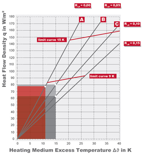
| test set-up» Klima WP 1000 including 5 mm system screed (SFM) overlap, heating pipe 8 x 1,1 mm, pipe distance 120 mm |
 |
|
|||||||||||||||||||||||||||||||||||||||||||||||||||||||||||||||
| Floor Covering | Thermal Resistivity | Average Temperature of Heating Medium | Achieved Heat Flow Density | |
| A | tile | 0,00 m² K/W | 31 °C | 78,0 W/m² |
| B | laminate | 0,05 m² K/W | 35 °C | 79,4 W/m² |
| C | strip parquet 22 mm | 0,10 m² K/W | 35 °C | 63,4 W/m² |
In order to avoid excessive surface temperatures, the flow temperature of floor systems with integrated heating needs to be set accordingly.
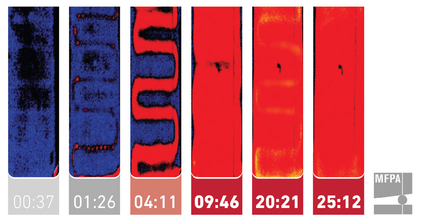
Time-dependent heat spreading (data in minutes) – tested and confirmed by MFPA Leipzig [Leipzig Institute for Materials Research and Testing].
 |
|
|||||||||||||||||||||||||||||||||||||||||||
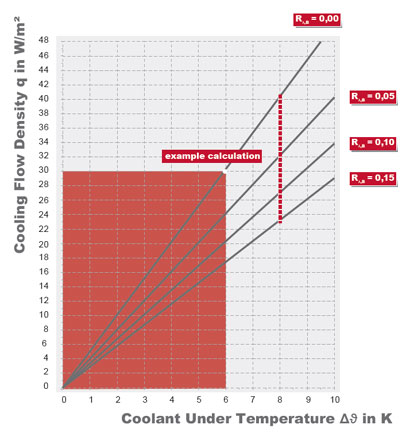
| Floor Covering | Flow Temperature | Return Flow Temperature | Cooling Flow Density |
| tile | 18 °C | 22 °C | ≈ 30 W/m² |
The cooling flow density has been determined based on the basic characteristic curve according to draft DIN EN 1264-5.
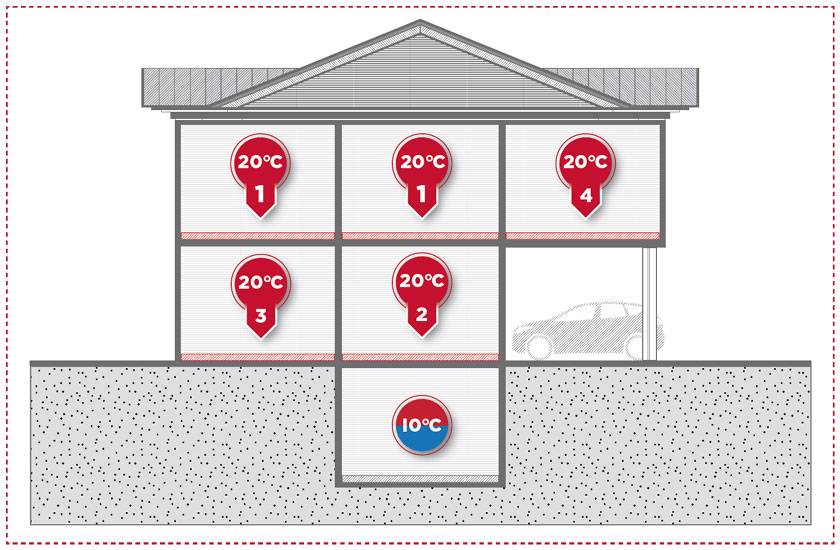
| Required Minimum Thickness in mm | |||||
| What is underneath? |
thermal resistivity R λ,FB in m²K/W lt. DIN EN 1264-4 |
wood fibre λD = 0,040 W/mK |
foamed polystyrene (EPS) λD = 0,035 W/mK |
polyurethane (PUR) double aluminium foil λD = 0,025 W/mK |
VIP vacuum insulation λD = 0,008 W/mK |
| case |
0,75 | 30 | 26 | 19 | 6 |
| case unheated / temporarily heated room / ground spoil |
1,25 | 50 | 44 | 31 | 10 |
| case T ≥ 0 °C |
1,25 | 50 | 44 | 31 | 10 |
| case 0 °C > T ≥ -5 °C |
1,50 | 60 | 53 | 38 | 12 |
| case -5 °C > T ≥ -15 °C |
2,00 | 80 | 70 | 50 | 16 |
In order to limit the energy consumption within a building both for new buildings as well as for the retrofit of old buildings, amongst others the thickness of the heat insulation needs to be considered.
For dimensioning the current Energy Saving Regulations are decisive. In Germany the Energy Saving Regulations EnEV 2009 respectively EnEV 2014 apply according to the date of the submitted building application until resp. after April 30th, 2014. In case the installation of the heat insulation is limited for technical reasons at the retrofit of old buildings, the requirements of the German Energy Saving Regulations are deemed to be complied with if the highest possible insulation thickness is fit according to the acknowledged rules of technology.
Detailed requirements for the heat conductivity of the insulation(s) can be found at the according applicable Energy Saving Regulations. The Requirements of DIN EN 1264-4 apply for the insulation underneath an underfloor heating.
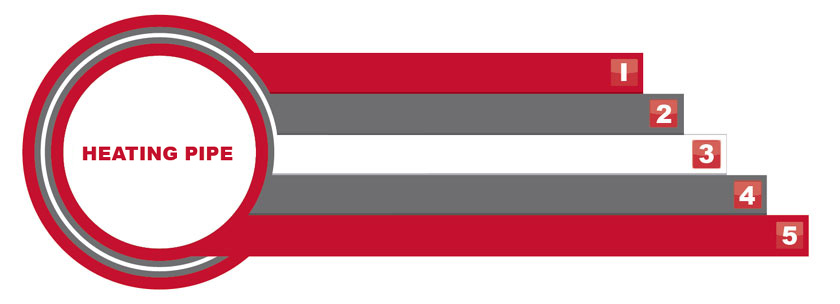
Flexible fully synthetic 5-layer compound pipe made of PE-RT 80 (Dowlex 2344) according to DIN 16833 and application standard DIN 4726. Oxygen impermeable according to DIN 4726 oxygen barrier protected between two PE-layers.
The pipe is approved as PEOC-SYSTEM with the corresponding fittings through DIN CERTCO, approval mark 3V217 PE-RT. The effidur heating pipe meets the requirements of ISO 10508: category 4 (underfloor heating, 6 bar).
The service life of a heating facility is essentially determined by the service life of the used metallic and non-metallic materials. The service life of metals is significantly distinguished by generating and preserving a thin protection layer of metal oxides. This surface layer inhibits corrosion so that a service life according to VDI 2067 is achieved. Nevertheless, chemical and physical processes can damage the protection layer.
For a long time the diffusion of oxygen through the pipes used in an underfloor heating was deemed negligible in comparison to other input possibilities. Experience shows that this factor shouldn’t be underestimated. The diffusing oxygen enhances the corrosion of the used metal parts that could lead to unintentional deposits within the heating system. This way the efficiency and functionality of the facility is lowered.
Therefore, the use of oxygen impermeable pipe, in the case of synthetic pipe with a reliably protected oxygen barrier, is indispensible in closed, technically gas proof heating systems. This also requires the regulation VDI 2035 sheet 2.
Effidur heating pipes have an organic oxygen barrier (EVOH) that limits the oxygen diffusion to approximately 0,1 mg / (m²d) and so undercuts the requirements of DIN 4726 (0,32 mg / (m²d)) many times.
The oxygen barrier is reliably protected from damage and humidity by the internal structure of the 5-layer compound pipe. Therefore externally sealing fittings can be used without problems.
When integrating an effidur floor heating or cooling system into an existing heating facility we recommend a hydraulic decoupling or the use of suited conditioning systems for the heating water (protection from lime and corrosion according to VDI 2035). The use of a flow filter additionally protects the heating system.
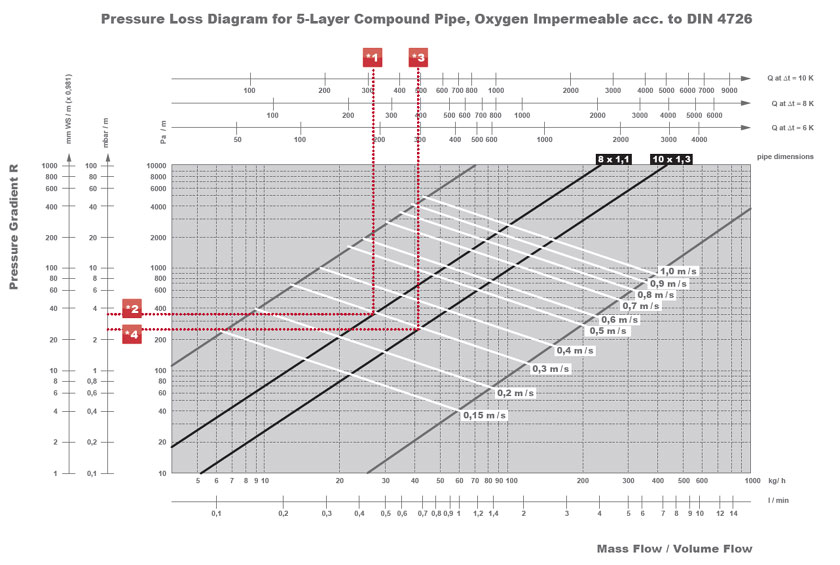
Pressure loss determination for an underfloor heating in order to calculate the required pump performance when connecting to an existing heating system. Since all heating loops are installed parallel and have the same length, the pressure loss for one loop per sub-manifold needs to be determined.
| heating pipe 8 x 1,1 mm | heating pipe 10 x 1,3 mm | ||
|
|
|||
|
|
|||
| local conditions | room size | 16 m² | 16 m² |
| pipe length per heating loop | 34 m | 68 m | |
| area per heating loop | 4 m² | 8 m² | |
| number of heating loops | 4 | 2 | |
| manifolds for flow and return flow | 2 x UV 4-8 | 2 x UV 2-10 | |
| further components | thermostatic valve (flow), return temperature limiter (return flow) | thermostatic valve (flow), return temperature limiter (return flow) | |
| required heat flow density | 80 W/m² | 60 W/m² | |
| total heat output per heating loop (*1 resp. *3 at chart) | 80 W/m² x 4 m² = 320 W | 60 W/m² x 8 m² = 480 W | |
| temperature difference (flow - return flow) | 10 K | 10 K | |
|
|
|||
|
|
|||
| pressure loss pipe | single value (*2 resp. *4 at chart) | 3,5 mbar / m | 2,5 mbar / m |
| total value per heating loop (single value x length of heating loop) | 119 mbar | 170 mbar | |
|
|
|||
|
|
|||
| pressure loss sub-manifold | value see chart "pressure loss of sub-manifold" | 2 x 5 mbar = 10 mbar | 2 x 5 mbar = 10 mbar |
|
|
|||
|
|
|||
| pressure loss components | 1 x thermostatic valve standard angled form at a mass flow rate of 110 resp. 82,5 kg/h | 100 mbar | 75 mbar |
| 1 x return temperature limiter standard angled form at a mass flow rate of 110 resp. 82,5 kg/h | 22 mbar | 17 mbar | |
|
|
|||
|
|
|||
| pressure loss total | sum of pressure losses pipe + manifolds + components | 251 mbar ≈ 0,25 bar | 272 mbar ≈ 0,27 bar |
| model | pressure loss | |
| single plug connector | STA AG-8 / STA IG-8 / STA IG-10 | ≈ 5 mbar |
| sub-manifold 2-port / 4-port | UV2-8 / UV 2-10 UV 4-8 / UV 4-10 |
≈ 5 mbar ≈ 5 mbar |
| manifold unit (= 2 x manifold bars) |
VBG 4 | ≈ 10 mbar |
| VBG 6 | ≈ 10 mbar |
The heating pipes can be connected through effidur single plug connectors, 2-port or 4-port sub-manifolds or with effidur multi-port manifold units. These manifolds can individually be equipped with control elements. You find a wide range of manifolds and pre-assembled control units at the chapter COMPONENTS/SUB-DISTRIBUTION resp. COMPONENTS/CONTROL UNIT. All manifolds of the effidur floor system have push connections with the John Guest principle. The manifolds might be installed in a wall recess or behind a dry wall in a distribution box. Pay attention to keep a minimum height of 200 mm between the distribution box and the floor.
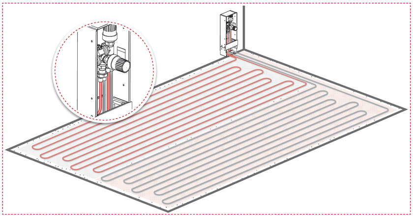
| Attention » The colouring of the heating loops is only to distinguish one from another and is not a connection model based on the temperature distribution! The drawing shows the connection of two heating loops to a control box » connection version 2 |
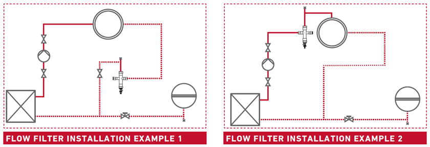
When connecting the underfloor heating to an existing heating system we recommend the use of a flow filter or sludge collector for the entire heating system or for the underfloor heating only. Depending on the project it might be more favorable to install the filter or sludge collector directly at the flow (example 2) instead of shown in our example 1. This way contaminations of the existing facility from the installation, dirt or similar can’t get into the loops of the underfloor heating. Pay attention to the manufacturer’s instructions.
For existing heating facilities it might be useful for hydraulic reasons to separate the underfloor heating from the existing radiator heating. The underfloor heating needs then to be hydraulically separated from the rest of the facility through a heat exchanger. This way the underfloor heating can ideally be run with a separate pump. Pay attention to the manufacturer’s instructions.

UWE KLEIN
Telefon +49 371 2399200
Telefax +49 371 2399229
eMail info@effidur.de

ZIP-SEARCH (Germany only)
Dieses Postleitzahlengebiet ist derzeitig nicht von unserem Außendienst besetzt. Unsere Ansprechpartner am Produktionsstandort beraten Sie gern.

JENS HACKE
Telefon +49 371 2399-205
Telefax +49 371 2399-230
Mobil +49 162 2022755
eMail jens.hacke@effidur.de


GERD KLIMKE
Dipl.-Ing. (FH)
Telefon +49 371 2399-252
Telefax +49 371 2399-253
Mobil +49 160 4790577
eMail gerd.klimke@effidur.de


THOMAS MÜLLER
Telefon +49 371 2399245
Telefax +49 371 2399229
Mobil +49 0172 9592838
eMail info@effidur.de


JAN BERGER
Telefon +49 371 2399 - 152
Telefax +49 371 8448208
eMail info@effidur.de

The information given on our products / onto this product page, in particular illustrations, descriptions, dimensions, weights and other parameters, is not binding. This is because technical progress means that our products are continually being developed and perfected. The user of our products is obliged to self-dependently verify and adhere to current technical guidelines, laws and provisions, even if they are not mentioned within our documentation. The general terms and conditions of business of effidur GmbH apply.
EFFIDUR GMBH
KURZE STRASSE 10
09117 CHEMNITZ
TEL +49 371 2399-200
FAX +49 371 2399-229
EMAIL INFO@EFFIDUR.DE

